Draw Steel Frame
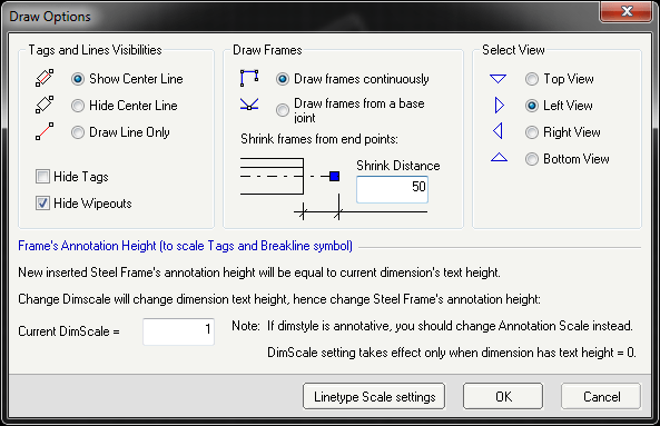 Draw Steel Frame Options window
+ Run command from Draw Palette
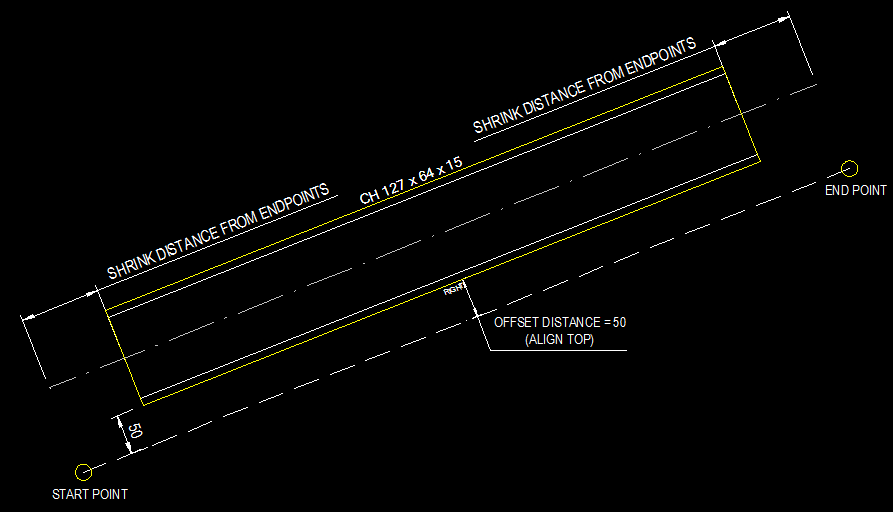
+ Pick Start Point, then End Point. New Steel Frame will be inserted
+ Type O and specify offset distance.
+ Type A to switch alignment
+ Type F to flip
+ Type V to open Draw Steel Frame Options window
+ Specify your preference visibility, shrink distance, view, new dimscale etc, then click OK
>>> New setting will be apply to current and next inserted Steel Frames
See also:
2. Tool Palette to edit Steel Frame block
Note:
+ You should use dimension style with text height of 2.5. This will help texts and dash lines look proportionally at the same time.
+ Sometime especially in drawing with imperial units, the linetype doesn't look right.
Before making drawing, you should change the linetype scale of each object inside the Steel Frame block definition by click to Draw Options > Linetype Scale Settings.
Convert lines and curves to Steel Frames
+ Run command from Draw Palette
+ Select lines and curves
+ Draw Steel Frame Options window will bring up for you to choose
+ Click OK to run the conversion
>>> Line will be converted to Steel Frame block.
>>> Curve (arc, circle, ellipse, polyline or spline) will be converted to frame drawn by the same object type.
After conversion, similar to Draw Steel Frame command, you can type V, A or F to change visibilities and alignment of new drawn objects.
Note: Converted objects from a curve is not editable through JTB Steel command. They are normal AutoCAD objects.